Verification of KRASTA models
In many cases a first version of a calculation model does not produce adequate results. In addition to false input data the abstraction of construction details may not be appropriate. Hence, checks of input data and results are essential during build and evaluation. There is no universal algorithm for these checks. This article describes various aspects of model checks and shall sensitize the KRASTA user for his work.
Visual control
After creation of mass and load cases in KRASTA a visual control is essential. Mass and load case are dragged from the object tree and dropped on the graphics window to show the masses and loads. Now the distribution within the structure and the resulting mass or load can be checked.
When a structure is modified, masses and loads can change accidentally because nodes or beams are created or deleted. It is strongly recommended to check all basic mass and load cases after modifications of the structure are finished.
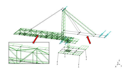
Fig. 1: Wind loads on the main boom are not complete, chord beams are missing in the wind load list. Wind loads are completely missing for the counter weight boom.
Plausibility check
If masses or loads are given per length or surface unit (e.g. live or product loads, wind) the resulting mass or load cannot be compared to the specification directly in many cases. A plausibility check can at least prevent larger mistakes.
For wind load the solidity ratio of the structure can be checked. Wind loads divided by the wind pressure result in an effective wind area. This area can be related to the outline of the structure. This solidity ratio can be compared with similar structures. A rough guess can also be helpful to verify the dimension of the wind load.
Furthermore, masses and loads on the same parts of the structure should be checked for the correct proportions. Masses on platforms (e.g. gratings) and live load can be applied on the same beam list. Resulting masses and loads in KRASTA need to have the same proportion as the masses and loads per surface unit. Wind loads in and out of service with different wind pressure can also be checked for similar proportions in similar working positions.
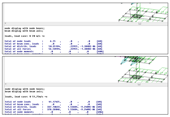
Fig. 2: Top: Wind load for 20 m/s wind speed, resulting load 56.5 kN. Bottom: Wind load for 51.75 m/s, resulting load 378.3 kN. The ratio of the squares of the wind pressure equals the ratio of the resulting loads.
Overlapping nodes and beams
After model geometry has been created or modified the model should be checked for double nodes and overlapping beams. The following menu items can be used:
"Construction" > "Check for..." "double nodes"
"Construction" > "Check for..." "double beams"
Caution: There are cases where nodes or beams overlap on purpose. These nodes and beams may not be melt.
Error messages during solver run
After a solver run the solver error log should be checked. (Menu: "Calculation" > "Show Log-File..."). Common error messages and warnings of the solver PAS are described in the KRASTA manual. Methods to find and eliminate the problems are also given there. Unfortunately PAS messages are available in German language only.
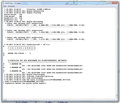
Fig. 3: Error messages of the solver in the calculation log.
Additionally newer versions of PAS IV provide an estimation of the condition number of the stiffness matrix. A large number (starting from 10E+08) may indicate weak fixation of degrees of freedom. Results from solver runs with a large condition number may be invalid due to numerical errors even if there is no further error message or warning.
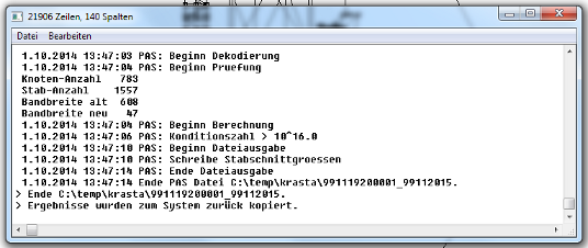
Fig. 4: Large condition number 10E+16, results need to be checked.
Numerical errors may often be detected by comparing loads and support reactions of load cases. Resulting loads and support reactions need to be the same in value and location. When differing significantly the model needs to be checked and modified. In many cases kinematically overdetermined beam structures made of rigid beams are the reason. Concerning the use of rigid cross sections the KRASTA manual gives some hints in chapter "Partial Rigid Cross Sections".
If beams are set inactive for the solver, loads on these beams may be included in the load display but not in the support reactions. The handling of inactive beams may be adjusted in the KRASTA options.
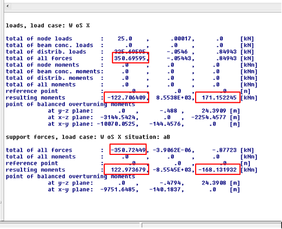
Fig. 5: Loads and support reactions differ significantly.
Bending line
Directly after a (successful) solver run the bending lines for selected load cases give a good impression of the behaviour of the structure. Unexpected deflections, sharp bends in false positions or even completely different bending lines as expected should be investigated. Joints or loads in false positions may be the reason or parts of the structure are not connected.
For beams without defined section points the bending line is linear from beam start to beam end. If beam results within a beam are relevant sections points have to be added accordingly.
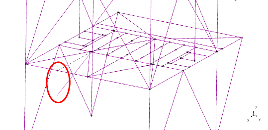
Fig. 6: Beams are not connected.
Check load paths
Important elements and parts for which the load transmission characteristic is defined should be checked in respect of that. Evaluation of inner forces at certain beam ends expose show false models.
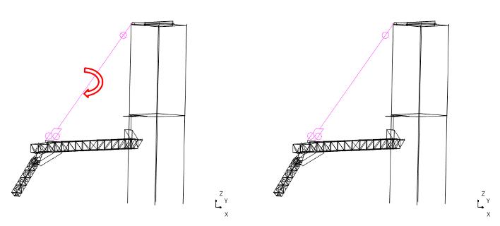
Fig. 7: The boom stay in the left model transfers torsional loads due to the fork at the lower end and the cardan joint at the top. This is not realistic and reduces boom strain. An additional torsional joint at the top (right model) is required.
Result expectations
Often the engineer has an expectation or a qualitative prospect of the results. If expectation and actual results differ, the discrepancy must be dissolved. The model could be false or the expectation of the engineer is not realistic. Both alternatives need to be considered.